High Voltage / Piezo Amplifiers & Signal Conditioners
Fiber Optic Links / Data Acquisition Systems
RF Power Amplifiers / Dual Directional Couplers
Instruments for Biological Science
Under Water Metal Detectors, Camera’s & Sonar Systems
|
Signal Conditioner
A - 308 Universal DIN Rail mounted LVDT Signal Conditioner
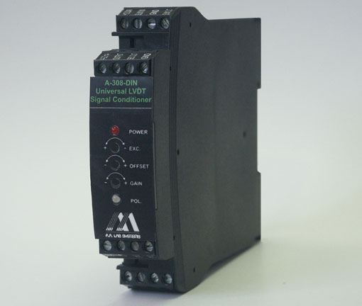
A - 308 is a High Accuracy, Low Cost, DIN Rail Mounted Signal Conditioner designed for any LVDT Application where an Analog DC voltage output or 4 - 20mA Current Output is required.
The units may also be used with any LVDT Sensor with 3, 4, 5 or 6 Wires, RVDT or Half Bridge Sensors (3 Wires).
The Universal Din Rail Mounted LVDT Signal Conditioner is a Stand-alone Unit. It is powered from +9 to +28V DC (switched by the user). The LVDT Transducer is connected to it via simple screw terminals. The unit will Output a Voltage which is Highly Linear (0.05%) to the Displacement (limited by LVDT sensor manufacturer’s specifications) or a 4 - 20mA Current Loop signal with the same Linearity. The unit is mounted in a standard DIN Rail case (22.5mm Width).
The LVDT Conditioner Boards are designed around High Accuracy ASIC that produces a Low Distortion Sine-wave Excitation for driving the LVDT Sensor. This ASIC also Demodulates the Signal from the LVDT Sensor and Converting it to a High Accuracy, Low Noise Signal, ready to interface with the Highest Accuracy A/D Converter Units. All Sensitive Components are Thermally coupled on the Silicon Chip Level, making the LVDT Conditioner almost Insensitive to Temperature Variations.
The LVDT Signal Conditioner Board is also insensitive to Excitation Level and Excitation Loading due to a State-of the-art Ratiometric Measurement Technology. The LVDT Excitation is measured at Real Time and the Output is Compensated in Real Time for any changes in Excitation Voltage Level.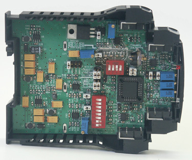
The A - 308 Boards can operate with almost any type of LVDT Sensor available when writing those lines. It’s Wide Dynamic range (with wide range GAIN and DC Offset controls) make it suitable for a Wide Range of LVDT Sensors Sensitivity. The Adjustment of these Controls is Very Easy and can be done by the user using a Small Screwdriver.
All setups are easy for a Non-trained user. Most common Excitation Frequencies can be set by user (16 settings) with Fine Tuning adjustment to match your Sensor’s Frequency. 4 Low Pass Filters limit the Output Noise and allow you to control the Dynamic Response of the sensor (50Hz, 100Hz, 250Hz, 500Hz).
The A - 308 DIN Rail Mounted LVDT Signal Conditioner may also operate with Very Long LVDT Wires by setting the Internal Lead/Lag Compensation Network (on board).
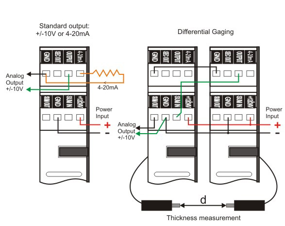
Precision Differential Gaging: Each unit features an Analog Input summed or subtracted from the modules reading for configuration of Difference or Addition of measurements (Thickness measurements etc.)
More than 1 Module can be configured together for synchronous operation of Multi-LVDT Sensors with the same Excitation Frequency and Phase (Master-Slave configuration).
Polarity LED indicator on front panel for easy center (Zero) setup.
|
What is “Ratiometric” measurement?
The LVDT Transducer contains a Primary Winding (input) where a Sine-wave Excitation is connected to and one or 2 Secondary Output Windings. If our conditioner board is measuring only the Output Voltage, we will call it a “Differential” Conditioner board. When we measure the Output Voltage (or the difference of the output windings) and divide it by the Excitation Voltage (or the sum of the output windings), then we call it “Ratiometric” Conditioner because we measure the ratio of the output to the input (Ratio = Vout / Vin).
|

|
- Block Diagram:
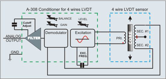
The A-308 is a High Accuracy, Low Cost Signal Conditioner, for use with most commercial LVDT sensors for Accurate Distance / Position Measurement. It's Small Size and High Accuracy makes it an Ideal Solution for many Applications.
- Features:
- Small Size
- Can be easily configured for 3, 4, 5, 6 wire LVDT / RVDT Sensors.
- Adjustable Gain, Offset, Excitation Level, Excitation Frequency, Bandwidth.
- 16 User Defined Excitation Frequencies with fine tuning adjustment. Non-Standard frequencies may be also configured at No charge.
- 4 Fixed Output Low - Pass Filters: 50Hz, 100Hz, 250Hz, 500Hz.
- High Linearity: 0.05%
- Can be used as Master or Slave Unit (for Multiple Sensor Operation using the Same Excitation Frequency and Phase, to avoid interference).
- Low Drift: <50ppm/°C of F.S.
- High Frequency Response: 50, 100, 250, 500Hz Standard, upto 20kHz Optional.
- Operates with Remote Sensor: upto 100m.
- Operation of Half-Bridge LVDT Transducer.
- DC Output proportional to position.
- Single supply Operation Voltage: 12V or 24V.
- Lead-Lag Phase Compensation for Long Cable Operation.
- Built-in controls of Frequency, Filter, Offset, Gain, Excitation
- Precision Differential Gaging: Analog “Math” Input is Added or Subtracted from Current Module Output Voltage (for connection of 2 Modules with 2 Sensors together)
Demodulator |
Bandwidth: |
50, 100, 250, 500Hz |
Linearity: |
Better than 0.05%; of FS |
Gain Drift: |
20ppm/°C of FS Max. |
Offset Drift: |
10ppm/°C of FS Max. |
Output: |
Unipolar or Bipolar |
LVDT Sensor Type: |
Any sensor with 3, 4, 5, 6 Wires |
Supply Voltage: |
+9 - 14V or +16 - 28V DC |
Output Voltage: |
±10V, 4 - 20mA |
General |
Primary to Secondary Phase Shift: |
Insensitive |
Transducer Null Voltage: |
Insensitive |
Transducer Cable Length: |
Upto 30m |
Output Cable Length: |
Upto 100m |
Excitation |
Excitation Range: |
3 - 20V RMS |
Excitation T.C.: |
100ppm/°C max |
Excitation Voltage Rejection: |
100ppm/dB |
Output Current: |
40mA RMS minimum |
Short Circuit Current: |
60mA |
Frequency Range: |
930Hz to 10KHz |
Excitation Frequency T.C.: |
200ppm/°C |
THD: |
−50dB |
Excitation current may be increased to 500mA (optional) |
Power Supply |
Voltage Range: |
+9 - 14V or 16 - 28V DC |
Current (@ No Load): |
40mA |
Temperature Range: |
0 - 70°C |
- Typical Applications:
- Connection of 3 / 4 / 5 / 6 Wire LVDT Sensors:
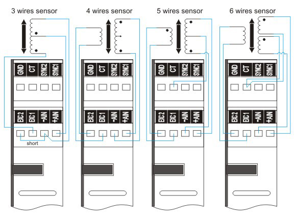
- ±10V or 4 - 20mA Output. Differential Measurements:
All Specifications are subject to change without a Prior Notice
For any sort of clarifications kindly contact:
info@globesolutionz.com
|